By Dan Wang, WG SA2 WI Rapporteur, China Mobile
First published May 2023, in Highlights Issue 06
To provide immersive experience for users, XR and Media services (XRM) are usually characterized by high data rate and low latency. 3GPP SA2 has started the XRM Work Item in Rel-18 to identify 5GS functionality and capability enhancements, including multi-modality transmission, 5G system (5GS) information exposure, PDU set-based QoS handling, uplink-downlink transmission coordination, Packet Delay Variation monitoring and reporting, and Power Saving enhancements.
Policy control enhancements to support multi-modality flows for single UE/multiple UEs
For XR services, there are multiple types of traffic, e.g. audio, video, sensor, pressure, and tactile, all generated to enhance the user experience. In the existing 5GS, the policy control is applied to a single data flow. To guarantee that the multi-modal data is transmitted in a coordinated fashion, the policy control of 5GS is now being enhanced with alignment policy control, e.g. same 5QI, same priority, or integrated network resource allocation.
5GS information exposure for XR/media service
The 5GS exposes network information towards it, which can assist an application to make timely adjustment to the media codec/traffic rate. There are two methods standardized:
Use of ECN marking for L4S
L4S (Low Latency, Low Loss and Scalable Throughput) is an evolution of explicit congestion notification (ECN). The L4S can be used in 5GS to perform ECN marking for the L4S services to report the congestion condition quickly to the application through the user plane, to facilitate the rate adaptation at the application layer.
The NG-RAN is responsible for detecting congestion, and NG-RAN or UPF performs ECN marking using the following options:
- NG-RAN detects the congestion and performs ECN marking for uplink and downlink in IP layer of the received packets, and then sends the packets to UE (downlink) and UPF (uplink).
- NG-RAN detects the congestion for uplink/downlink flow and sends the latest congestion information to UPF. Based on received congestion report, the UPF performs ECN marking for uplink and downlink IP layer of the received packets.
API based information exposure towards AF
The 5GS information, including congestion information, QoS Notification Control, and data rate are generated in NG-RAN and sent to SMF/PCF/NEF/AF for general exposure or sent to UPF/local NEF/AF for low-latency exposure. What’s more, UPF can also calculate the data rate and expose it by using the above two exposure paths. The round-trip-delay for multiple QoS flows are reported from UPF to PCF and exposed to NEF/AF.
Besides the above parameters, 5GS also supports the exposure of the estimated bandwidth based on the NWDAF calculation, providing more information to the application server.
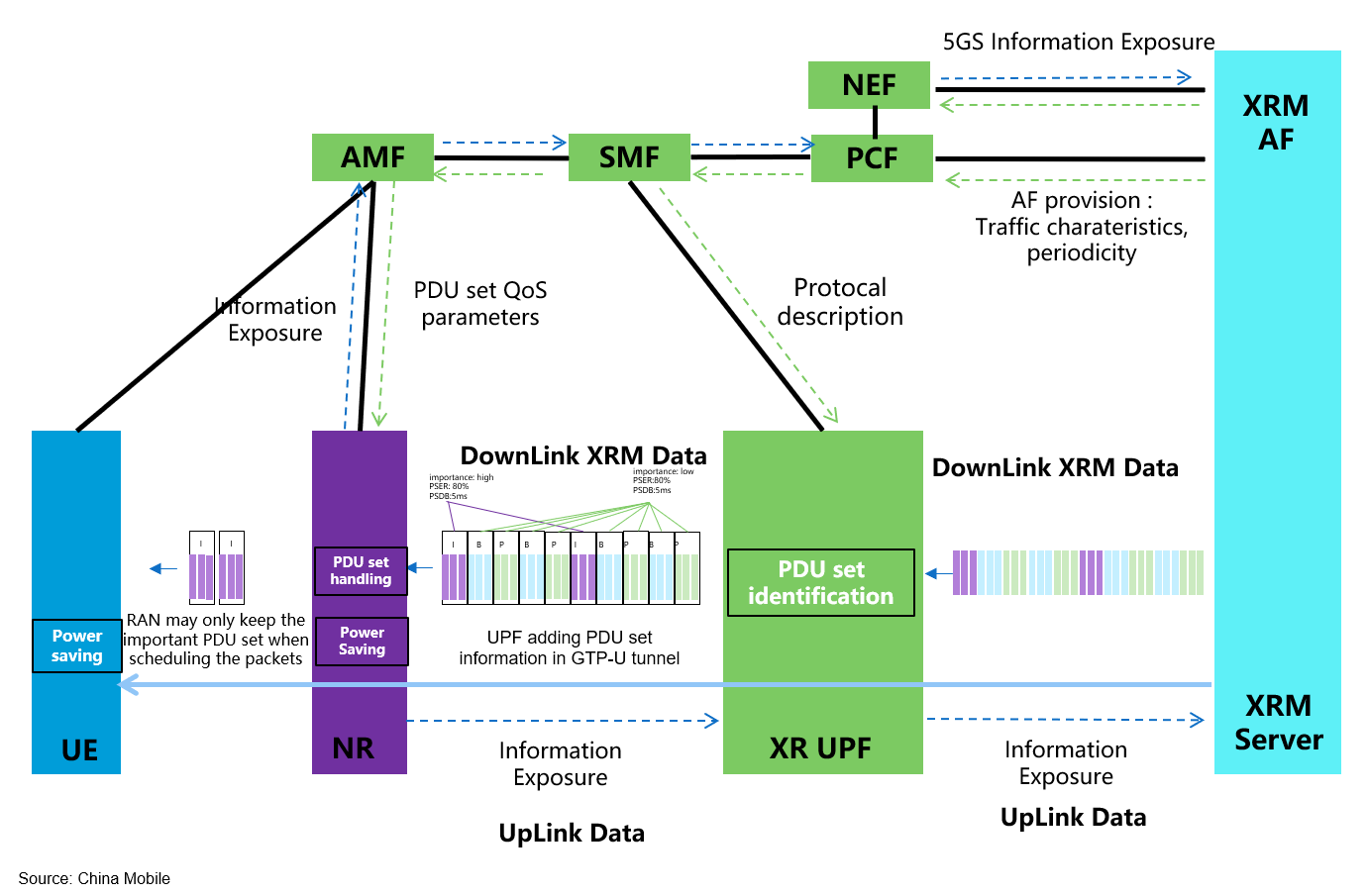
Support PDU set based QoS handling including PDU set integrated handling and differentiated handling
In traditional mobile network since GPRS, the QoS control is based on the concept of flow and packet. However, such scheduling didn’t consider the relationship between packets, which are important for especially interactive media services like XR, since it’s common that one unit of media layer needs to be delivered via multiple packets. Furthermore, different media units may contribute differently to the user experience even they are within a single steam. Thus the importance of these media units is not unique from media layer point of view.
To support the above integrated and differentiated transmission of media units (e.g. a frame or a video slice), a PDU Set concept is introduced to denote the collection of packets (i.e. PDU, Protocol Data Unit in 5G) carrying a media unit. The 5GC obtains the following information to support PDU Set level QoS handling:
- PDU Set information, including PDU Set Sequence Number, End PDU of the PDU Set, PDU Sequence Number within a PDU Set, PDU Set Size and PDU Set importance.
- PDU Set level QoS parameters. PDU Set Delay Budget (PSDB) and PDU Set Error Rate (PSER) are introduced to control the delay and error rate on PDU Set level instead of PDU level.
Uplink-Downlink transmission coordination to meet round-trip latency requirements
In 5G system, the AF provides RT latency requirements together with a RT latency indication to the PCF, which indicates the service data flow needs to meet that the RT delay overhead doesn't exceed the RT latency requirement. The PCF is responsible to split the RT latency into an UL PDB and a DL PDB. The restriction is that the UL PDB and DL PDB can be unequal but their sum shall not exceed the RT latency. The PCF generates two PCC rules for UL stream and DL stream and assigns the 5QIs according to PDBs respectively.
Packet Delay Variation monitoring and reporting
In 5G system, the AF provides Packet Delay Variation requirement for specific QoS flow. The PDV can show the network transmission stability. Once the PCF accept the PDV requirement, the corresponding PCC rules for QoS monitoring can be generated and sent to SMF to trigger the QoS monitoring for packet delay. When the PCF receives the packet delay values, the PCF itself can calculate the PDV based on IETF RFC 1889 or 3393.
UE power savings for XR services based on network assistant information
XR terminals, e.g. glass or headset, usually handle dense computation demands with very limited battery. Power saving is an outstanding issue to resolve for such terminals. For most XR and media service, the media stream follows a roughly periodicity. For example, a 60 fps video is composed of continual bursts with 16.67ms periodicity. Considering the periodicity, the RAN/terminal can consider the CDRX cycle length to match the arrival time of the media packets better to save the power.
Another important information is the end of burst, with this RAN can understand the end of transmission and therefore indicate UE to enter power saving state immediately.
Based on above analysis, 5GC can provide periodicities and N6 jitter range of media services to RAN node via control plane signals, and also end of burst indication to RAN node via user plane packet. With the above information, RAN can generate an appropriate CDRX configuration to enable suitable power saving behavior without impact on traffic delivery.
Acronyms:
|
5QI |
5G quality of service identifiers |
|
AF |
Application Function |
|
AMF |
Access & Mobility Management Function |
|
CDRX |
Connected mode discontinuous reception |
|
GPRS |
3GPP General Packet Radio Service |
|
N6 |
The N6 Reference point is between the UPF (UP Function) and a Data Network. |
|
NEF |
Network Exposure Function |
|
NWDAF |
Network Data Analytics Function |
|
PCF |
Policy Control Function |
|
PDB |
Packet Delay Budget |
|
PDV |
Packet Delay Variation |
|
RT delay/latency |
Real Time |
|
SA2 |
3GPP Working Group System Architecture and Services (TSG SA WG2) |
|
SMF |
Session Management Function |
|
UPF |
User Plane Function |
|
XR |
eXtended Reality |
|
XRM |
XR and Media services |
Further reading:
Please be aware that this page is a snapshot of the work going on in 3GPP at the time of writing. The full up-to-date picture of all work is contained in the Work Plan (https://www.3gpp.org/ftp/Information/WORK_PLAN/)
 Technology