by Wang Fei (Rapporteur, China Mobile) and Kyungjun Choi (Samsung)
First published Nov 2023, in Highlights Issue 07
3GPP WG RAN1 has now completed its study on the evolution of NR duplex operation (TR38.858). This article presents RAN1’s key findings.
SubBand non-overlapping Full Duplex (SBFD) is an attractive solution for the uplink (UL) bottlenecks in the legacy Time Division Duplex (TDD) scheme, by introducing simultaneous transmission and reception at the gNB side. The solution has been studied for decades outside 3GPP and the time is now right for 3GPP to consider the feasibility of SBFD from the performance, implementation and specification perspective.
The NR system has been widely and successfully deployed on TDD bands of Sub-6GHz and mmWave, but there is a continuous demand from operators for improvement of UL performance of the TDD bands. In Rel-18 NR Duplex Evolution study item, SBFD at the gNB side within a conventional TDD band was studied to allow the simultaneous existence of Downlink (DL) and Uplink (UL) in different frequency subbands.
New interference and CLI handling schemes
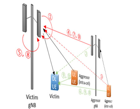
SBFD and flexible/dynamic TDD allow DL/UL transmission from gNB/User equipment (UE) at the same time, introducing new interference types (Figure 1). The proper modelling of these interferences is crucial for adequate performance evaluation. In this study, cross link interference (CLI) handling schemes for SBFD and flexible/dynamic TDD are also studied and evaluated.
The Design/Specification perspective
Study assumptions and Basic SBFD operations
It is assumed SBFD operation is within a TDD carrier and within a single configured DL and UL BWP pair with aligned center frequencies. Non-SBFD aware UEs, including legacy UEs, and SBFD aware UEs can coexist in cells with SBFD operation at the gNB side. Up to one UL subband (located at one side or middle of the carrier) and up to two DL subbands are assumed in a SBFD symbol configured as DL or flexible.
At least for RRC_CONNECTED state, it was concluded both time and frequency locations of subbands for SBFD operation are known to SBFD aware UEs. UE behaviors for non-SBFD aware UEs follow existing specifications, and new UE behaviors can be introduced for SBFD aware UEs.
SBFD subband(s) configurations
Semi-static time/frequency subband configuration with the same subband frequency resources across different SBFD symbols was studied as baseline. Whether a slot can consist of both SBFD and non-SBFD symbols was also studied. In order to avoid frequent transition between SBFD and non-SBFD symbols, potential limitation on the maximum number of transition points can be considered from a SBFD subband configuration perspective. A maximum of two transition points within a TDD configuration can be considered.
Semi-static SBFD and Dynamic SBFD
RAN1 studied whether to allow transmission/reception within/outside subbands for a SBFD aware UE, and identified semi-static SBFD and dynamic SBFD. For semi-static SBFD, DL reception is only allowed in DL subband and UL transmission is only allowed in UL subband in DL/flexible symbol. For dynamic SBFD, DL reception outside DL subband(s) and/or UL transmission outside UL subband may or may not be allowed in flexible symbol.
Dynamic SBFD can better adapt to the UL/DL resource requirements based on UL/DL traffic loads, but may increase implementation/scheduling complexity and CLI, incur loss of resources, and can result in additional specification impact.
Transmission and reception across SBFD symbol and non-SBFD symbol
The impact and potential enhancements for UL transmissions and DL receptions across SBFD symbols and non-SBFD symbols were studied. Potential enhancements include resource allocation enhancements in time, frequency, power and spatial domain. RAN1 studied whether for a SBFD aware UE to allow transmission/reception across SBFD and non-SBFD symbols in the same or different slots. Also, RAN1 studied unaligned frequency boundaries and frequency resource allocation enhancements in case of the transmissions/receptions in SBFD and non-SBFD symbols with different available resources. In addition, RAN1 concluded that separate resources, frequency hopping parameters, UL power control parameters and/or beam/spatial relation may be beneficial on SBFD and non-SBFD symbols.
CLI handling schemes for SBFD and Flexible/Dynamic TDD
RAN1 identified and evaluated the following inter-gNB/UE CLI handling schemes for SBFD and flexible/dynamic TDD:
- Inter-gNB/UE co-channel CLI measurement and/or channel measurement and reporting
- Coordinated scheduling for time/frequency resources between gNBs
- Spatial domain coordination method
- UE and gNB transmission and reception timing
- Power control scheme based on gNB/UE transmission power adjustment
Performance evaluation results and analysis
Key Evaluation Assumptions
System level evaluation was performed to see performance benefits of SBFD over static TDD. Non-coexistence case (one single operator), co-channel co-existence case (2-layer topology for a single operator with macro layer using static TDD and indoor layer using SBFD) and adjacent-channel co-existence case (two operators using two adjacent carriers with one operator using static TDD and the other operator using SBFD) were evaluated. For all cases, the same SBFD configuration was assumed amongst all gNBs.
Four alternatives were considered regarding the TDD and SBFD configurations and corresponding DL/UL resource ratio, where X represents a SBFD slot and the numbers are UL resource ratio.
- Alt-1: {DDDSU} for static TDD (20%) and {DXXXU} for SBFD (32%)
- Alt-2: {DDDSU} for static TDD (20%) and {XXXXU} for SBFD (35%)
- Alt-3: {DDSUU} for static TDD (40%) and {XXXXU} for SBFD (40%)
- Alt-4: {DDDSU} for static TDD (20%) and {XXXXX} for SBFD (20%)
Key assumptions were used for drawing observations and conclusions, e.g., 1dB desense for gNB self-interference suppression capability, twice the total number of antenna elements and same total number of TxRUs for gNB antenna configuration, piece-wise linear model as a function of the total received power for BS noise figure.
System-Level Performance of Semi-static SBFD
RAN1 concluded semi-static SBFD provides user-perceived throughput (UPT) gain in specific evaluation scenarios, as summarized in Table 1. RAN1 concluded that the DL/UL UPT gain of SBFD with XXXXX comes from more DL/UL transmission opportunities. For SBFD with XXXXU, the UL UPT gain comes from more UL resources and more UL transmission opportunities and the DL UPT loss comes from less DL resources. Also, the UL UPT loss comes from gNB-gNB CLI and noise figure increase due to higher blocker power and the DL UPT loss comes from UE-UE CLI.
Note: no less than 93dB for FR1 UMa and Dense UMa and no less than 98dB for FR2-1 Dense UMa are assumed for co-site inter-sector spatial + digital isolation capability
UL Coverage Gain of Semi-static SBFD
Link level evaluation was performed to evaluate UL coverage improvement of SBFD with XXXXU over TDD with DDDSU. Based on the assumption of 1dB desense for gNB self-interference suppression capability and different co-site inter-sector isolation values, RAN1 observed semi-static SBFD with PUSCH repetition type A provides the UL coverage gain of 5.41dB in FR1 UMa and 6.92dB in FR2-1 Dense UMa, respectively.
Further reading & resources:
TR 38.858 Study on evolution of NR duplex operation
IMPORTANT NOTE: Please be aware that these pages are a snapshot of the work going on in 3GPP. The full picture of all work is contained in the Work Plan (https://www.3gpp.org/ftp/Information/WORK_PLAN/). Look for Acronym 'NR_duplex'.


 Technology


