
Energy Efficiency in
3GPP technologies
- Jul 08, 2024
- Last Updated Apr 08, 2025
- 10257 Views
By Alain Sultan, 3GPP MCC
Overall context
As per [0]: In 2023, the EU adopted a set of Commission proposals to make the EU's climate, energy, transport and taxation policies fit for reducing net GreenHouse Gas (GHG) emissions by at least 55% by 2030, compared to 1990 levels.
All industry segments are focussing on limiting their consumption, and telecommunications, representing 2 to 3 % of the global energy, is no exception (see [1], [2], [3], [4]).
In parallel, and focussing on telecommunications, the International Telecommunication Union (ITU) has set a 45% reduction of GHG emissions between 2020 and 2030.
The ITU clarifies that mobile telecommunication produces 9% of the total of Information and Communications Technology (ICT) CO2 emissions (in 2007[0a]).
Linking these data together, mobile telecommunication – which is what 3GPP defines and addresses – emits about 0.2 to 0.3% of the worldwide CO2 emissions. As a percentage, this value might sound rather insignificant, but, in absolute terms, this represents about 100 million of (metric) tons per year [0b], i.e. the equivalence of Greece emissions, or of 4 million trees absorption [0c].
Besides, further than contributing to these worldwide objectives for reducing GHG emissions, reducing the power consumption for telecoms also offers the immediate benefit to operators to limit their operational costs (OPEX).
3GPP involvement
Since Release 10 in 2011, 3GPP has been monitoring and providing solutions for several energy efficiency aspects of its systems: starting with 3G, then 4G and now 5G. It started with a few general studies and advice. In the recent Releases, this aspect is taking more and more place in the definition of the system.
Although not formally identified by 3GPP (only in this document), three main aspects of 3GPP’s work relating to energy efficiency / energy saving can be distinguished:
- Proposing solutions and practical advice on how to operate the system as to limit its energy consumption, while keeping (almost) a same level of service. These are presented in Technical Recommendations (TRs) since they do not impact so-to-say the system.
- Defining functionalities specifically targeted to save energy, e.g. commands to reduce/turn off the power of less used/unused base stations (e.g. at off-peak). These are defined in Technical Specifications (TSs).
- “Keeping in mind” the energy-efficiency aspect when designing (all interfaces of) the 3GPP standard, e.g. not to mandate to send regular location updates for a user equipment known to be static, as a vending machine.
The first point, energy saving recommendations, is rather related to energy savings (“turn off the light when you leave”). These recommendations are presented all along the document, for different contexts and different generations of mobile systems. Even if 3GPP defines the interfaces and not the inner structure of network equipment (nor mobile phones), recommendations are sometimes given to the manufacturers on possible hints to reduce the power consumption of their equipment.
The second point, energy saving specific procedures, is somewhere between energy saving and energy efficiency (it would be like: “define automated ways to detect that the light is still on when nobody is there”). The border between the second and third categories (specific to energy efficiency or not) might sometimes be blurry. The mechanisms that go with these procedures, e.g. allowing to get feedback of the network consumption, are also presented. These are mostly in the Operation, Administration and Maintenance (OAM) domain.
The third point, writing an energy-efficient standard, is rather energy efficiency (“define an efficient light bulb”). This is much more subtle -if possible at all- to handle. E.g. energy efficiency was a key driver when defining the 3GPP support for IoT (Internet of Thing)/MTC (Machine Types of Communications)/RedCap (Reduced Capacity). Yet, it is also quite vague: not only “energy efficiency” is a quite relative concept, but it is everywhere and nowhere in particular, since virtually all 3GPP decisions do consider efficiency at some point.
The two first types of energy-related aspects of 3GPP are described here. The last type is not covered here, except for notorious cases.
More Deep Dives
Early 3G and 4G radio recommendations (Release 10)
General radio recommendations and Single layer (no overlay) coverage
Two TRs provide energy saving recommendations for the radio in Rel-10: TR 25.927 [5] describes some general principle and proposes solutions, while TR 36.927 [6] proposes other solutions, and introduces other solutions, specific to overlay coverage, i.e. where the coverage is provided simultaneously by a basic, wider-area, cell coverage while smaller cells are also deployed to boost the coverage on hot spots.
TR 25.927 [5] reminds that the base station accounts up to 80% of CO2 emission in a mobile network and the majority is due to the radio elements. It then proposes four sets of solutions to decrease this power consumption, namely: Dormant mode, Secondary antenna deactivation, Power control of common channels and Cell DTX.
Dormant mode refers to switch off one or more carriers. Deactivating a carrier may make it possible for Node B to either power down or completely shut off one of its Power Amplifiers (PAs), which are one of the elements in the Node B that consumes a significant amount of power. The savings are highly implementation dependent, in particular the case when a multi-carrier PA (MCPA) is employed.
Secondary antenna deactivation can be used only in the context of Multiple-Input Multiple-Output (MIMO) antennas, that uses multiple antennas as to use spatial diversity. It simply consists in turning off MIMO by keeping the main antenna.
Power control of common channels modulates the power to match only what is needed to cover the active User Equipment’s, as shown in the figures below.
Figure 1: Cell coverage without power control of common channels, all UEs are within the coverage

Figure 2: Cell coverage with power control of common channels, all active UEs are within the coverage while number of idle UEs fall out of coverage

With Cell DTX, the idea is to periodically turn off the power amplifier (PA). All the downlink channels need to be shut down simultaneously in order to be able to turn off the PA and achieve significant energy saving benefits. The larger the off-duration percentage compared to the overall operation time, the larger the energy saving.
These four recommendations are simply guidance to the 3G Base Stations manufacturers, and nothing was mandated. One can note that several of these solutions are not 3G-specific and can be applied in later generations.
Besides the recommendations of TR 25.927 [5], TR 36.927[6] also covers single layer coverage (as well as the overlay scenarios detailed in next section).
TR 36.927 [6] reminds that a traditional strategy to cover densely populated areas, while ensuring high bit-rate services to the users, is to introduce small cells as to have a dense mesh of radio cells. As a consequence, a given UE can be in visibility of several cells, which is generally a problem, and that is avoided by purposely limiting the power of the cells. This is the top diagram of Figure 3:
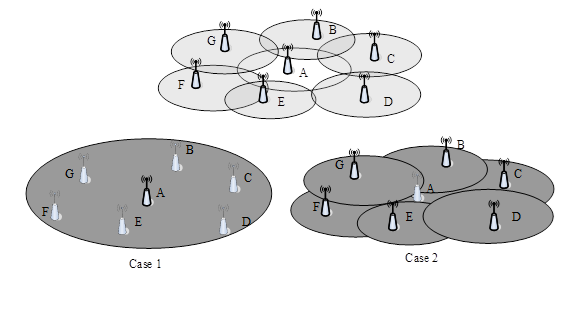
Figure 3. energy saving in a context of single layer (dense) coverage
However, at off-peak time, the two lower diagrams of Figure 3 show that, to save energy, several cells might be turned off: in Case 1, only cell A is kept “on” and its power is considerably increased. In Case 2, on the contrary, cell A is turned off and the power of all its neighbouring cells is slightly increased as to cover the area previously covered by cell A. The cells which power is increased are called “compensation cells” while the ones turned off are called “energy saving cells”. Of course, in each case, the total increased power for the compensation cells is still less than the power saved by turning off the energy saving cells.
This mechanism is controlled by OAM and/or by a signalling-based approach.
For the OAM-based approach, cells are preconfigured as potential compensation cells and energy saving cells. The decision to switch is based on proprietary algorithms in each cell configured by OAM. The neighbour nodes should be informed either by the OAM or by the signalling.
In the signalling-based method, the cells are aware of whether they are compensation cell or energy saving cell based on OAM and/or proprietary information , e.g. UE measurements, interference status, load information etc. When the energy saving cell decides to enter dormant mode autonomously or based on information exchanged with the compensation cell, it will initialise communication with the corresponding compensation cells, and the coverage related information may be included into the request message. The final decision is made at the compensation cell and the feedback may be needed. Furthermore, similar cell switching on procedure specified in Rel-9 as captured in TS 36.300 [7] could be reused.
Specific solutions for overlay cells coverage
TR 36.927[6] also covers overlay cells coverage, both for intra-4G scenarios and for scenarios with combined 4G and pre-4G (3G/2G) coverage, as shown in the Figure 4.
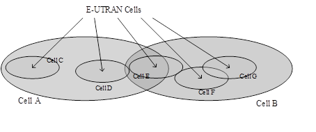
Figure 4: cell coverage overlays
Cells C, D, E, F and G are eNBs (i.e. E-UTRAN/4G base stations) deployed to locally boost the capacity of the basic, wider-area, coverage provided by cells A and B. Cells A and B can be also eNBs (intra-RAT/inter-eNB scenario) or from a legacy Radio Access Technology (RAT), either 3G/UMTS or 2G/GSM, i.e. they are respectively a NB or a BTS (inter-RAT scenario).
The energy saving consists of turning off/on the smaller eNBs (cells C to G) as to have them active only when needed, i.e. to have a precise control of switching of entering/exiting dormant mode for these cells.
Here also, two types of solutions are studied: an OAM-based or a signalling-based approach.
In the OAM-based approach, this switch is based on centralized OAM decisions, which are made based on statistical information obtained from coverage and/or GERAN/UTRAN/E-UTRAN cells, e.g. load information, traffic QCI, etc. The OAM decisions can be pre-configured or directly signalled to the EUTRAN cells. Whenever a switch happens in an eNB, its intra/inter-RAT neighbour nodes should be informed either via OAM or signalling.
In the signalling-based approach, the switch is decided autonomously or based on information exchanging with the bigger coverage cell (A or B). Switch off decisions/requests will be based on information locally available in the EUTRAN node, including load information of both the coverage and E-UTRAN cells. Switch-on may be performed based upon requests from one or more neighbour inter-RAT nodes, or based on internal EUTRAN node policies (periodic switch on, max switch off time, etc,). Neighbouring cells should also be informed after any switch. To perform energy saving more efficiently, some energy saving parameters may be exchanged between inter-RAT neighbour cells if required, e.g. traffic thresholds, time duration, power consumption and so on.
Outcome of these studies:
This has been continued in Rel-12 by RAN3 under the work “Study on Energy Saving Enhancement for E-UTRAN”, shown later in this document.
General OAM and network management recommendations (Releases 10 and 11)
Preliminary Studies
Two studies were conducted in respectively Rel-10 and Rel-11 – and not re-published after – on OAM and network managements aspects of energy saving. These are TR 32.826 [8] (Rel-10) on “Study on Energy Savings Management (ESM)” and TR 32.834 [9] (Rel-11) on “Study on Operations, Administration and Maintenance (OAM) aspects of inter-Radio-Access-Technology (RAT) energy saving”.
TR 32.826 [8] provides general considerations of Energy Savings Management (ESM), including the overlay scenario and the single-layer turning on/off of cells scenario. One can note its figure on reduced power consumption provided by the “compensation and energy saving” cells mechanisms presented above. It shows how the “traffic load” (blue dotted line) can be used to reduce the power consumption (red and green curves – unfortunately, the different units are not shown in the TR):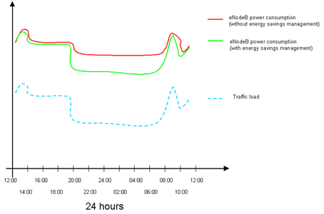
Figure 5: traffic load versus power consumption
TR 32.834 [9] focuses on Inter-RAT aspects of Energy Saving, i.e. reducing the capabilities of one RAT to reduce its energy consumption while providing a back-up by another RAT. It introduces some concepts later used in the TSs presented below.
First series of OAM TSs on Energy Saving
TR 32.826 [8] and 32.834 [9] are preliminary work that has led to a specific 3GPP SA5 (OAM group) TS handled, namely the “Stage 1” document TS 32.551 [10] (“Energy Savings Management (ESM); Concepts and Requirements”). The Stages 2 and 3 for Energy Savings Management are not covered by dedicated TSs but impact several existing TSs (TS 32.522 [11], TS 32.762 [12], TS 32.642 [13] and TS 32.652 [14]).
TS 32.551 [10] provides some general concepts and requirements on energy savings functionalities, and indicates whether a requirement is met via the Interface N or via other means.
The Interface N (Itf-N) is defined TS 32.102 [15] to be between the Network Entities (NE) Management and the Network Management/Service Management (NM/SM) Operations System Function (OSF), as shown in the picture below.
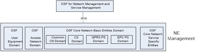
Figure 6: Overview of 3GPP Telecom Management Domains and Itf-N
For the general concepts, it introduces Centralized Energy Saving (ES) versus Distributed ES.
For Centralized ES, the ES algorithms are executed in the OAM system. Centralized ES has two variants: NM-Centralized ES or EM-Centralized ES, where ES algorithms are executed respectively at the Network Management (NM) level or at the Element Management (EM) level.
For Distributed ES, the ES algorithms are executed directly at the Network Element (NE) level.
The three different levels of management (i.e. NM, EM and NE) are not specific to ESM but are general OAM concepts: they are shown in the context of Load Balancing in the next figure.
As shown on the two figures, the itf-N is between the (centralised) NM and (distributed) DM parts of the OSF, so it is within the OSF (and not between OSF and NE). The next figure, on LB, shows it more clearly, with OSF elements in pale red and the Network Elements (eNB in this case) in greenish color: the itf-N is between two sets of pale red elements.
Back to Energy Saving, the key concepts of ESM are that a cell (or whatever other network element) may be on one of these two states: notEnergySaving state or energySaving state. The two corresponding elementary procedures are Energy saving activation (change from notEnergySaving to energySaving state) and deactivation (opposite change). For selected ESM use cases, a third state is possible: compensatingForEnergySaving. This state applies to an off-peak traffic situation, where a network element is remaining powered on, e.g. taking over the coverage areas of neighbour base station in energySaving state.
With these concepts established, TS 32.522 [11], TS 32.762 [12] and TS 32.642 [13] describe the Stage 2. These 3 TSs are not specific to Energy Saving but they are impacted by energy saving aspects.
TS 32.522 [11] describes the Information Service (IS) at the Network Resource Model (NRM) Integration Reference Point (IRP), in a Self-Organizing Networks (SON) context.
As seen in previous sections, a major aspect of Energy Saving is to be able to turn off some cells whenever possible, offloading its load to neighbouring cells. Consequently, a proper control of cells’ Load Balancing (LB) is a key aspect of Energy Saving.
The overall architecture for Load Balancing (LB) functionalities is provided by TS 32.522 [11]:
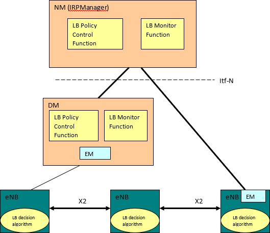
Figure 7: Overview of LB architecture
Load Balancing is impacted by energy saving but is not specific to ES. LB is actually one of the key aspects of SON, and more information on LB is found in the SON documentation.
TS 32.522 [11] introduces the EnergySavingProperties Information Object Class (IOC). An IOC is a concept widely used in OAM field. To understand it, it is necessary to understand how, generally speaking, Managed Object (MO) are handled in OAM. A MO is a software object that encapsulates the manageable characteristics and behaviour of a particular Network Resource. The MO is instance of a class defined in a MIM (Management Information Model)/NRM (Network Resource Model). This class, called Information Object Class (IOC), has attributes that provide information used to characterize the objects that belong to the class. Furthermore, the IOC can have operations that represent the behaviour relevant for that class.
The EnergySavingProperties IOC, representing the energy saving properties of a network element supporting Energy Saving Management functionality, has 3 attributes (besides its identity): energySavingState (mandatory), energySavingControl (conditional) and isProbingCapable (optional).
This TS also provides guidance on how to handle two energy saving-related cases: conflict between energy saving and cell outage compensation; and Coordination among Cell Outage Compensation, Capacity and Coverage Optimization, and Energy Saving Management
About the conflict between energy saving and cell outage compensation, the following case is meant: one or more candidate cells are configured to possibly take coverage of the original cell. The original cell is in energySaving state or is about to enter energySaving state. One or more candidate cells go into outage with the consequence that coverage of the original cell can not be provided any more.
When this occurs: the original cell in energySaving state shall leave energySaving state; if the original cell is about to enter energySaving state, it shall not go into energySaving state until candidate cell outage is recovered and candidate cell is able to provide the coverage; the original cell may go into the energySaving state after the candidate cell outage is recovered and coverage of the original cell can be taken over by candidate cell again.
The second scenario is a general SON coordination problem (not specific to energy saving).
TS 32.762 [12] and 32.642 [13] are also not energy saving-specific documents.
TS 32.762 [12] is part of a set of specifications defining E-UTRAN NRM IRP Requirements. This specific TS defines the relevant Information Service (IS), by reusing some parts of the Generic NRM IRP IS, either by direct reuse or sub-classing and, in addition to that, defines E-UTRAN specific IOCs. Its relationship with Energy Saving is limited to show how the EnergySavingProperties IOC is used.
TR 32.642 [13] specifies the UTRAN network resource information that can be communicated between an IRPAgent and one or several IRPManagers for network management purposes. It specifies the semantics and behaviour of information object class attributes and relations visible across the reference point in a protocol and technology neutral way. It does not define their syntax and encoding. Here again, Its relationship with Energy Saving is limited to show how the EnergySavingProperties IOC and related attributes (isESCoveredBy and isChangeForEnergySavingAllowed) are used in the overall OAM context.
Note that TS 32.762 [12] and 32.642 [13] have not been continued after Release 11.
CT1’s TR 24.826 [16] studies the impact on the UE of switch-off of radio equipment on the network side: a UE currently being served by the radio equipment subject to switch-off will have to find an alternative, either in the same RAT ("intra-RAT energy saving", which is the preferred case), or in another RAT ("inter-RAT energy saving", which is the fall-back mechanism), assuming that an alternative radio access can indeed be found. All the cases of RAT cell being switched off (source radio) and the new RAT cell (target radio) are studied, leading to the following table:
Table 1: Combinations of source and target radio for energy saving (for UE attached for PS services) and possible procedures after switch-off of source radio
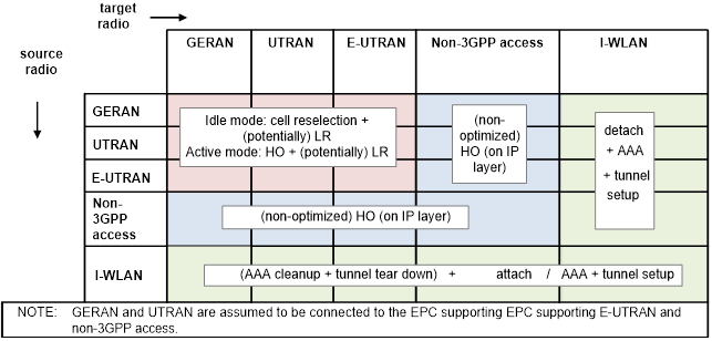
Acronyms used in the table above:
- HO = Hand Over
- LR = Location Request
- AAA= Authentication, Authorization and Accounting (used in non-3GPP systems)
The main diagonal of this matrix describes intra-RAT energy saving, and the non-diagonal elements constitute inter-RAT energy saving. A characteristic difference between the two directions of switching, i.e. between switching off and switching on an access network, is that with the latter the UE in case of non-optimized handover is not immediately forced to act, because it ends up in having more choices for access networks than before.
The procedures listed in the table above are either fully standardized and optimized behaviour within 3GPP RATs (GERAN, UTRAN, E-UTRAN), or non- or only partially standardized and optimized behaviour (if either source or target radio access is not a 3GPP access).
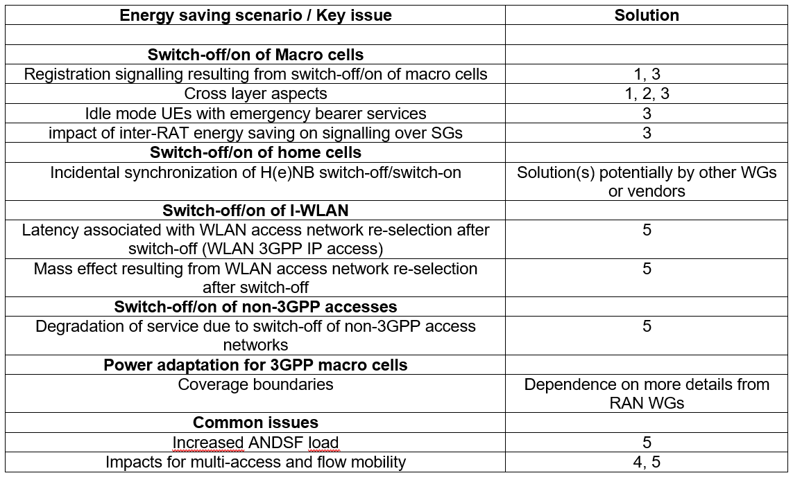
The TR studies the problems resulting on the UE behaviour of switching off/on the 3GPP macro cells (i.e. the “normal”, public, outdoor, cells) in particular for the cases presented above with “energy saving and compensation” cells, i.e. the cells being respectively turned off for energy saving and the ones taking over the traffic, and their power adaptation, also presented above. Some more specific cases are also studied: the switching off/on of 3GPP home cells (i.e. covered by (e)HNB), of WLAN access networks in 3GPP I-WLAN, of non-3GPP access networks (e.g. WIMAX).
Five solutions are proposed to all these problems identified:
Solution 1. Optimized configuration of tracking areas and TAI lists: in the overall configuration of Tracking Area (TAs) in the network or TA Identifiers (TAI) lists assigned to UEs, the cells targeted for switch off are preferably avoided on boundaries of TAs or boundaries of the areas defined by TAI lists, respectively. This has no impact on 3GPP TSs.
Solution 2. Adding time dependence to configuration settings in Mos: time parameters are added to the configuration parameters. As an example, if the E-UTRAN is to be switched off at 24:00 h, the voice domain preference could be set to "CS Voice only" for a time window which starts sufficiently long before the target time for switch-off, e.g. to 23:40 h. This solution impacts TS 24.167 [17] and TS 24.216 [18], and enhancements in specifications of corresponding procedures (TS 24.301 [19] and 3GPP TS 24.237 [20]).
Solution 3. Dynamic radio access network sharing: this solution consists in re-using the work specified for Multi-Operator Core Network (MOCN), defined in TS 23.251 [21], is a slightly different context: in “normal” MOCN, one RAN is shared between several CNs operators and entities. Here, each operator has its own CN and RAN: say operator 1 has RAN1 and CN1, same for operator 2 with RAN2 and CN2. Now, the two operators sign agreements to share their resources, so that RAN1 is connected to both CN1 and CN2, and RAN2 is connected to both CN1 and CN2. So we are back in the MOCN usual context for each RAN. Each operator turns off their RAN at different pre-agreed times, and MOCN is used whenever RAN1 or RAN2 is turned off, as shown in the figure below:
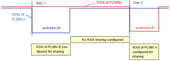
Figure 8: Dynamic network sharing scheme for energy saving (two operators)
For this solution too, there is no impacts on the normative part of 3GPP work.
Solution 4. Network-based handling for multi-access and flow mobility. It addresses the rather specific problem of risk of signalling overload to the PDN GW/Home Agent when multiple UEs send a DSMIPv6 Binding Update following the removal of an access network. The solution is to enhance the Home Agent functionality in the PDN GW by some knowledge about availability of access networks. The already existing procedure "network initiated removal of an access network from a PDN connection" as specified in TS 24.303 [22] is used to redistribute the IP flows via the access networks remaining operational, in a smooth manner and early enough. To this end, the Binding Revocation Indication (BRI) messages sent to all affected UEs could be spread out over time, while still allowing completion of the process before the access network is switched off.
Solution 5. Activation times in ANDSF data. The ANDSF (Access Network Discovery and Selection Function) is an entity that assist the UE to discover non-3GPP access networks such as Wi-Fi or WIMAX. It can be overloaded when a 3GPP RAT is turned off. To avoid this, either the data provided by the ANDSF (i.e. access network discovery information data, stored and provided by for non-3GPP access networks) is enhanced with activation status information (activation time windows) or the activation times of access networks are considered implicitly with all relevant ISMP and ISRP rules. The first variant implies slight changes to TS 24.302 [23] and possibly TS 23.261 [24], while the second variant implies no change.
TR 24.826 [16] concludes by providing a table of key issues and their associated solution:
Table 2: Key issues and solutions
UE Power Saving Mode
“UE Power Saving Mode (PSM)” is defined in TS 23.682 [25] (“Architecture enhancements to facilitate communications with packet data networks and applications”): A UE may adopt the PSM for reducing its power consumption. That mode is similar to power-off, but the UE remains registered with the network and there is no need to re-attach or re-establish PDN connections. A UE in PSM is not immediately reachable for mobile terminating services. A UE using PSM is available for mobile terminating services during the time it is in connected mode and for the period of an Active Time that is after the connected mode. The connected mode is caused by a mobile originated event like data transfer or signalling, e.g. after a periodic TAU/RAU procedure. PSM is therefore intended for UEs that are expecting only infrequent mobile originating and terminating services and that can accept a corresponding latency in the mobile terminating communication.
The Stage 3 is implemented in particular in TS 25.413 [26] with a “Power Saving Indicator” and in 36.300 [27].
Other Release 11 Energy Saving aspects
The two Rel-11 work items on energy saving “Core part: Network Energy Saving for E-UTRAN” and “GERAN part: Network Energy Saving for E-UTRAN” contributed to the overall system design, with no particular concrete output in Release 11.
The first one is said to have impacted 4 TSs: 25.413 [28] (“UTRAN Iu interface; RAN Application Part (RANAP) signalling”), 36.300 [27] (“E-UTRA and E-UTRAN Overall description; Stage 2”), 36.413 [29] (“E-UTRAN S1 Application Protocol (S1AP)”) and 36.423 [30] (“E-UTRAN X2 Application Protocol (X2AP)”). For 25.413 [28], there was only a Rel-13 CR entitled “Power Saving enhancements for UMTS”. TS 36.300 [27] defines, on the X2 interface (between two neighbour eNBs), an Energy Saving function, which allows decreasing energy consumption by enabling indication of cell activation/deactivation, as seen in previous sections. Energy saving indicators are also considered in the general designs in 36.413 [29] and 36.423 [30].
The second one is said to have impacted TS 48.018 [31] (Serving GPRS Support Node (SGSN); BSS GPRS protocol (BSSGP)) but only one Energy saving CR was found, and this was in Rel-15: “Energy efficiency enhancements for EC-GSM-IoT MS in idle mode”.
Release 12 on Energy Saving
Study on System Enhancements for Energy Efficiency (SA2)
This Study is covered by Rel-12’s TR 23.866 [32], which, as all the other 3GPP 800-series (internal) studies, was not republished for later Releases. This TR considers four different “Energy Efficient Deployment Scenarios”.
Again, these are deployment scenarios, with minimum/no impact on the 3GPP Specification work.
Scenario 1: Pooled deployment of MMEs
The separation into user and control plane network entities enables separate deployments of those network entities. In the scenario described here the user plane network entities are deployed more distributed, i.e. topologically closer to the RAN to optimise the routing and reduce the required transmission resources. The control plane network entities MME are deployed as a pool of MMEs to take advantage from the pooling effects, like better scaling or possibilities to distribute traffic between different nodes. On the other hand, pooled MMEs will cover a larger geographical area compared to a single MME deployment and therefore resulting in less MME changes compared to a single MME deployment. As these single MMEs most probably will be deployed at different locations, the single MME deployment will result in increased inter-MME transmission effort compared to a pooled deployment.
A drawback of that pooled deployment of MMEs is that some considerable signalling traffic may occur between eNBs, S-GWs and MMEs. In contrast to the transmission resource gains in the user plane this increases transmission efforts for the control plane as the user plane nodes and the MMEs are deployed at topologically different locations.
The pooled deployment of MMEs is supported by already defined standards. Any potential optimisations for reducing the signalling traffic, that may run long distance with such deployments, need further study.
Concerns were raised for the Service Request change proposal excluding the MME and having the SGW to store the information to be used for the subsequent Service Requests. The SGW needs to support new protocols such as SCTP, S1-AP and NAS, if trying to avoid impacts for eNB.
Scenario 2: Energy efficient node utilization through load re-distribution during off-peak times
In this deployment scenario, it is assumed that the operator has configured pools of MMEs and/or S-GWs to serve the EUTRAN. These resource pools are typically dimensioned for peak loads. This means that the number of user plane gateways (e.g. S-GW and P-GW) and control plane entities (e.g. MME) deployed and operated are dimensioned according to the maximum number of UEs and their traffic demand.
During off-peak time, most of these pooled entities can be turned off since the remaining (not turned off) entity(ies) have enough capacity to cope with the remaining traffic load, as shown in the figure below, extracted from the already-presented above TR 32.826 [8]: on this figure, the traffic load during 23:00 and 7:00 (blue bars) is less than 2%. Since the entity can cope with 5 times more then, if a traffic redistribution is possible, 4 entities out of 5 can be turned off during this off-peak time, and the remaining 5th one can support all the remaining traffic. Between 4:00 and 6:00, it is at least 95% of the network entities that can be turned off (if traffic redistribution would have been possible on such a large scale, which is generally not the case).
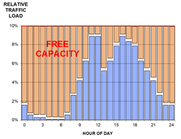
Figure 9: Typical daily traffic load variation
In order to allow energy savings by switching unnecessary core network resources/nodes to energy conservation mode during off-peak times, load re-distribution mechanisms are needed that allow the network to move users/sessions from underutilized core network nodes (e.g. P-GW, S-GW, MME, eNB) to other nodes either by OAM or based on DNS.
However, TR 23.866 [32] does fully analyse the necessary enhancements for MME and SGW load re-distribution for active mode UEs. Also, the potential impacts on RAN have not been investigated for active mode UEs.
Scenario 3: Energy Efficiency by Network Sharing
In areas with low density of population, even the minimum PLMN configuration may provide more resources than actually needed. In these areas, network sharing features will provide energy efficiency. This sharing can be done statically (permanently) or dynamically, i.e. only during the off-peak times of the day.
This is quite similar to solution 3 of TR 24.826 [16], presented above, the difference being that solution 3 relies on ‘national roaming’ between operators, where each operator remains the unique owner of his network. Here, with ‘RAN sharing’, the RAN entities are shared.
The use of such sharing approaches may depend on regional, legal or licence conditions that may determine permission or obligations for network sharing in general.
The variant of dynamic sharing may cause peaks in signalling traffic during the change between sharing and non-sharing configurations.
Scenario 4: Energy Efficiency by Scheduled Communications
RAN developed approaches with inter-RAT energy saving. There may be however devices that are single RAT, e.g. some devices for machine type communications. Those devices cannot move to another RAT, but may need to communicate only during regular intervals, like considered under time controlled communications for MTC.
Here again, this can be achieved without any system enhancements: a scheduled RAT switch-off/on may happen controlled by O&M.
Conclusions of this study
It was not possible during the study period to derive quantitative metrics for measuring the gains of approaches for improved energy efficiency as the base figures of energy consumptions are largely determined by the specific product implementations. The study concludes that features that are designed for load or network sharing, like pooling of core network nodes, can be deployed also for energy efficiency purposes. The efficiency is gained mainly from better scaling granularity, e.g. less needs for over-provisioning, and from sharing base functionality, like power supply or other site equipment, which reduces also base power consumption.
As a conclusion we may determine that it seems more promising to consider energy efficiency or also resource efficiency during the design of any new feature or functionality, e.g. with regard to required storage, signalling or processing resources. Larger effects may be obtained when designing a new system. Hence energy efficiency should be one of the main system design guidelines.
Study on Energy Saving Enhancement for E-UTRAN (RAN3)
This study is covered by Rel-12-only’s TR 36.887 [33], which identifies potential solutions for energy saving scenarios, both for LTE “single-layer” coverage and for overlay coverage, and to perform their initial evaluation so that a subset of them can be used as the basis for further investigation and standardization.
It studies more in depth the different scenarios presented earlier in this document, in the section “Early 3G and 4G radio recommendations (Release 10)”, i.e. “Inter-eNB energy saving enhancement for overlaid scenario”, “Single compensating eNB deployment scenario” and “Multiple compensating eNBs deployment scenario”, respectively described in the above sections “Specific solutions for overlay cells coverage”, and in “General radio recommendations and Single layer (no overlay) coverage” (left and right cases of Figure 3).
It confirms that all these scenarios are indeed possible. The annexes contain some simulation results for power consumption gains that can be achieved.
For the overlaid scenario, the two different layers are 800MHz and 2600MHz deployed in the same area. The deep sleep mode selection process will be based on the 2600MHz layer.
As shown in the figure 10 , a maximum of 27.72% power saving is reached at off-peak time.
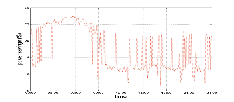
Figure 10: Total network energy savings during the day
For the “single-layer” (non-overlapping) coverage scenario, the energy savings are up to 22%. Assuming 8 hours of low traffic per day, this leads to a potential overall gain of 16%.
The TR also mentions in its annexes some other “hints” for energy saving, more directed to vendor, for their specific hardware implementation and deployment (and then outside of 3GPP scope), such as:
Improved cell hardware: Power amplifiers based on operating point adaptation and on deactivation of amplifier stages. An adaptive power supply unit enables the adaptation and deactivation of the transceiver components and the PA. The Small Signal RF transceiver allows the deactivation of some of its components during time periods of no signal transmission. Finally, the digital transceiver provides the signal conditioning features and the control signals to the transceiver components for their adaptation and deactivation.
Micro DTX (discontinuous transmission): This radio interface technique, enabled by improved cell hardware as described above, allows when no user data is transmitted, to deactivate the radio (micro sleep mode) between transmissions of cell specific reference symbols.
It also mentions “antenna muting”, which is the solution already mentioned above that consists in turning off (some of) the secondaries antennas in a MIMO context, hence (partly) disabling MIMO.
Release 13 on Energy Saving
Study on Solutions for GSM/EDGE BTS Energy Saving (GERAN1, GERAN2)
The single study on Energy Saving for 2nd generation (GSM) has been conducted in Rel-13, in TR 45.926 [34] (as a 900-series, this Rel-13 TR has been re-published for all subsequent Releases).
As for later generations, the most energy-consuming part of the antenna site (called “Base Transceiver Station” in 2G, equivalent to later generations’ (e)NB) is for the radio equipment (RE), so this is what is studied in this TR. More precisely, the RF output power reduction for the BCCH (Broadcast Control Channel) carrier is investigated for different scenarios, in regard to traffic load profiles (low load, medium term load and busy hour load) and site configurations (three sectorized sites with 2 TRX, 4TRX and 8 TRX per cells). Two solutions are proposed:
BCCH Carrier Power Reduction:
it reduces the transmit power on the BCCH carrier for idle timeslots and for timeslots used for traffic channels. Two variants are investigated on when to apply the power reduction for traffic channels: only for DTX silence periods (variant 1) or both for DTX silence and active periods (variant 2). The level of power reduction of 2 dB against the reference case (not applying any power reduction) was evaluated for both variants for different load profiles and different site configurations. The candidate has impacts to network KPI. The total handover number slightly decreases when it is applied. The percentage of satisfied users may decrease but be within a 95% target in most cases, especially when the reference case meets the target. It also has limited impacts to the call drop rate.
It was observed that the investigated power reduction for the BCCH carrier is up to 12.5 % for the small site configuration S(2/2/2) and up to 10 % for the medium site configuration S(4/4/4), respectively.
Output Power Reduction on BCCH Carrier for GMSK:
It applies a reduced output power on the BCCH carrier for all time slots carrying GMSK modulation except time slots carrying BCCH and CCCH channels as well as timeslots preceding them. For the latter a limited power reduction of up to 2 dB is proposed, whilst for the other time slots a reduction in the range 2 dB to 6 dB is proposed. The considered APD range 2dB…6 dB, which is identical to that one allowed for higher order modulations on BCCH carrier will generally have a positive impact on call quality metrics – such as satisfied user rates, handover failures and call drops – when compared against the reference case not applying any power reduction on BCCH carrier. In addition a small positive impact on cell reselection performance in idle mode is observed.
In regard to power consumption metrics, the candidate solution for small and medium size configurations at different traffic loads and for MS velocities of 3 km/h and 50 km/h has shown to yield improvements in output power reduction up to 2.8 dB and savings in cumulated TRX power consumption up to 16 % for the small site configuration S(2/2/2) and up to 9 % for the medium site configuration S(4/4/4), respectively, which is considered to be substantial.
The impact on the normative work is to allow the network to configure the BCCH carrier power save mode for the purpose of network energy savings.
Other Rel-13 work on Energy Efficiency
SA5 has slightly modified its TS 32.425 [35] on “E-UTRAN Performance Management (PM); Performance measurements” to take into account the Energy Efficiency related Performance Measurements.
It is just clarified that it is important to differentiate if the cell unavailability or the failure of the RRC connection establishment happens because of Energy Saving as Energy Saving Management feature is activated by the Operator on purpose.Such failures should be distinguishable from other network failures, therefore should be counted separately. With the separate cell unavailability counter due to Energy Saving. It makes it possible to deduct the cell downtime due to Energy Savings from the total cell outage.
Release 14 on Energy Saving
There was no dedicated work item on Energy Saving (nor or Energy Efficiency) in Rel-14. This does not mean that no work was done, but the related work was covered under another “umbrella”, e.g. the support for Cellular Internet of Things, as presented in Rel-15.
Release 15 on Energy Saving
Introduction
In Release 15 and the introduction of the 5G network, and the worldwide interest increased on energy efficiency, the 3GPP work on this topic has changed scale, going from one topic handled in one/a few WGs (mostly SA5, but also some RAN WGs) to a key design for the system, impacting all 3GPP groups.
In Rel-15 alone, four studies were dedicated to Energy Efficiency / Energy Saving: one directly handled by TSG SA plenary – which is rather unusual in 3GPP, since technical work is usually done at Working Groups level, but this shows how important the Energy Efficiency aspects are for 3GPP – and three handled by SA5.
Definition of Energy Efficiency
From Rel-15 onwards, the definition of Energy Efficiency is clarified. The definition does not come from 3GPP but from ETSI Technical Committee EE, in the ETSI ES 203 228 [36] (“Environmental Engineering (EE); Assessment of mobile network energy efficiency”). The Energy Efficiency KPI for network elements are expressed in terms of:
Energy Efficiency (NE) = Data Volume divided by the Energy Consumption
This is also shown by the formula:
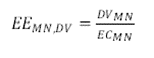
where DV is the Data Volume, expressed in bit, transported across a network element. The Data Volume measurements are collected via OAM. EC is the Energy Consumption, expressed in Joule, of the same network element. MN stands for Mobile Network.
This formula is reminded in several 3GPP TSs and TRs dealing with energy efficiency.
In the case of radio access networks, an EE KPI variant may also be used, expressed by:
Energy Efficiency (RAN) = Coverage Area divided by the Energy Consumption
the Energy Consumption being the one of the RAN elements.
SA plenary study: Study on Energy Efficiency Aspects of 3GPP Standards
TR 21.866, covering SA’s study, is a rather theoretical document, which for instance defines the total Energy Efficiency of a 3GPP system as the sum of Energy Efficiencies per deployment scenario (dense urban, urban, rural, highway, indoor hotspot, etc), which in turn is defined as the sum of traffic load points over the Energy Consumption weighted by a coefficient in consideration of the traffic load per each scenario. The traffic load measurement points with their corresponding weight for each traffic load point depend on the location of the system-wide EE control and measurement and network configurations.
The TR concludes that Energy Efficiency in a 3GPP network is a combination of: Coordinated Energy Saving in RAN and other subsystem in 3GPP Systems, Power Consumption Reduction at the Site Level, Energy Efficiency in 3GPP systems with NFV, Energy Efficiency in Self-Organizing Networks and Energy Efficiency Achievement by Context Data Analysis.
SA5 Rel-15 work on Energy Efficiency
Control and monitoring of Power, Energy and Environmental (PEE) parameters in Radio Access Networks (RAN) (PEE_CMON)
PEE_CMON specifies how OA&M supports the control and monitoring of Power, Energy and Environmental (PEE) parameters in pre-5G Radio Access Networks (RAN). It specifies an OA&M architecture and interfaces to support such capabilities. It relies on EE KPIs for Radio Access Networks, as well as their measurement methods, as they have been defined jointly by ETSI TC EE and ITU-T SG5. Collected parameters serve as input for calculating the Energy Efficiency KPI of live base stations, as defined by ETSI TC EE.
This work item specifies the requirements on the interface between the Remote Management Server (RMS) (cf. ETSI ES 202 336-12 [37]), located at the NM layer, and either the 3GPP Domain Manager (DM), or a Power, Energy and Environmental (PEE) XCU/DGU (XML enabled CU / Data Gathering Unit) (cf. ETSI ES 202 336-12 [37]), or a Vendor-Specific Remote Management Server (VS-RMS), so as to enable the control and monitoring of PEE parameters of 2G, 3G and LTE base stations having either built-in PEE sensors or external PEE sensors. It also specifies the protocol-independent information model. Finally, it produces a solution set based on (HTTP-based) REST / JSON.
In Rel-15, SA5 also performed two studies: “Study on OAM support for assessment of energy efficiency in mobile access networks” (FS_OAM_EE) and “Study on system and functional aspects of Energy Efficiency in 5G networks” (FS_EE_5G). The second one was finally moved to Rel-16, so only FS_OAM_EE was left in Rel-15.
Study on OAM support for assessment of energy efficiency in mobile access networks (FS_OAM_EE)
This study is covered in TR 32.856 [38], which identifies how 3GPP TSs can meet the requirements expressed by the ETSI Technical Committee EE for assessing the energy efficiency of radio access networks.
A gap analysis is provided between ETSI ES 203 228 [36] and 3GPP Technical Specifications.
TR 32.856 [38] starts from ETSI ES 203 228’s [36] KPI for the assessment of energy efficiency:
![]()
And provides means to calculate DVMN and ECMN in the case of a 3GPP network.
Both values are calculated via OAM. ECMN is calculated via control and monitoring of PEE parameters through a described OA&M architecture, in the two cases where base stations are equipped with embedded or external sensors.
A potential overall OA&M architecture is presented for collecting data volume measurements and energy consumption metrics into a single application / database at the network management layer. Two subcases are distinguished: the general case and the case with vendor-specific RMS. The potential overall architecture for the control and monitoring of the energy consumption of radio access networks is shown in the next figure.
Figure 11 provides a high-level description of the global OA&M architecture for a/ the collection of data volume measurements and b/ the control / monitoring of PEE parameters, in the case of both base stations with embedded sensors and base stations with external sensors being deployed. This architecture illustrates the case when the operator deploys external sensors with their vendor-specific RMS (connected via vendor-specific interface). As several vendor-specific RMSs can potentially be deployed within an operator’s network, an “umbrella RMS” (non-vendor-specific) is deployed.
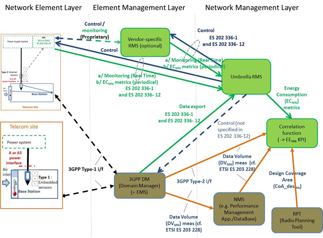
Figure 11: Potential overall architecture for the assessment of the energy efficiency of radio access network (all types of base stations)
The Umbrella RMS is a Network Management layer Remote Management Server in charge of controlling and monitoring Power, Energy and Environmental parameters of base stations.
The Vendor-specific RMS is an optional Element Management layer Remote Management Server in charge of controlling and monitoring Power, Energy and Environmental parameters of base stations. It may have proprietary interfaces with PEE XCU/DGUs.
The TR concludes that a new set of specifications shall be defined to support the interfaces between: PEE XCU/DGU and Umbrella RMS; Vendor-specific RMS and Umbrella RMS; 3GPP DM and Umbrella RMS. This work was continued in Rel-16 under the work item “Energy efficiency of 5G” EE_5G (and its preliminary Feasibility Study FS_EE_5G), described below.
Further enhancements for Extended Coverage GSM for support of Cellular Internet of Things
Extended Coverage GSM for support of Internet of Things (EC-GSM-IoT) was conducted by RAN WG6, ex-GERAN. It is an evolution of EGPRS providing a streamlined protocol implementation, reducing MS complexity while supporting energy efficient operation with extended coverage compared to GPRS/EGPRS. EC-GSM-IoT improves the coverage performance of Cellular IoT devices by 20 dB compared to EGPRS along and enables long battery life time achieved by energy efficient methods over the radio interface. The extended coverage is achieved by a high number of blind physical layer transmissions along with modified channel coding schemes.
In Release 13, the base station supporting EC-GSM-IoT requires minimum 4 consecutive timeslot resources reserved for packet data operation to support extended coverage operation. Furthermore, the coverage improvement for low power EC-GSM-IoT devices with 23 dBm output power is limited to 10 dB in this release.
In Release 14, as part of radio interface enhancements, EC operation with a reduced number of 2 consecutive timeslot resources both on DL and UL specified. In addition, a new uplink coverage class CC5 is added to improve the MCL performance in uplink by 4 dB compared to Release 13, which can be mapped both to 4 and 2 consecutive time slot resources.
In Release 15, as part of further enhancements, a paging indication channel for EC operation is introduced as well as the deferred system information acquisition procedure for EC operation both targeting the improvement of energy consumption of the device in idle mode. The deferred system information acquisition procedure was also specified for Power Efficient Operation (PEO) devices that operate in normal coverage with increased power consumption efficiency in idle mode due to adoption of Extended DRX and relaxed mobility requirements. In Release 12, are still ongoing at the time this document is written. As such, no stable summary can be provided.
Even further enhanced MTC for LTE
This work item, conducted by 3GPP WG RAN1 and 4, builds on the LTE features for Machine-Type Communications (MTC) introduced in Rel-13 and Rel-14 (e.g., low-complexity UE categories M1 and M2, and Coverage Enhancement Modes A and B) by adding support for new use cases and general improvements with respect to latency, power consumption, spectral efficiency, and access control.
The following clauses describe the new MTC features for LTE in Rel-15. All features are optional for the UE and can be supported by Cat-M1 and Cat-M2 and by normal LTE UEs supporting CE mode unless otherwise stated. All features are applicable to both CE modes (A and B) in all duplex modes (HD-FDD, FD-FDD, and TDD) unless otherwise stated.
The key functionality to be noted here is “Lower UE power class”: to enable support of use cases associated with small device form factor and low power consumption (e.g. wearables), a new lower UE power class with a maximum transmission power of 14 dBm is introduced for Cat-M1 and Cat-M2, together with signalling support for the lower maximum transmit power with appropriate coverage relaxations.
Release 16 on Energy Saving
SA5 Rel-16 work on Energy Efficiency
“Study on system and functional aspects of Energy Efficiency in 5G networks” (FS_EE_5G), initiated planned for Rel-15, was finally moved to Rel-16, although this was not corrected in the 3GPP Work Plan. The study led to normative work referenced by “Energy Efficiency in 5G networks” (EE_5G), described below.
Study on system and functional aspects of Energy Efficiency in 5G networks (FS_EE_5G)
The study, in TR 32.972 [39], was initiated for Rel-15 but was finally done for Rel-16, in the same Release as the normative work.
TR 32.972 [39] is a continuation of the work presented above on FS_OAM_EE (covered by TR 32.856 [38]) dealing with how the work initiated by other SDOs / working groups on pre-5G and/or 5G radio access networks energy efficiency translate into a 5G network.
Here again, the starting point is the formula:
![]()
The data volumes (DVMN) for 5G network elements / functions are collected using a measurement method (reportingMethod), specified in TS 28.550 [40] for stage 1, stage 2 and stage 3. The measurements (e.g. counters) are defined in TS 28.552 [41] for the 5G radio access network and the 5G core network.
The Energy Consumption (ECMN) is collected using power meters, or via built-in sensors enabling the collection of energy consumption measurements via OAM, or via external sensors.
This TR proposes to restrict the 5G Energy saving management only to the NG-RAN because the radio access network energy consumption represents the largest portion of the total operators' network energy consumption. Besides, the use cases for energy saving in the 5G core network are not available. In this context, it reminds that the architecture of an NG-RAN is:
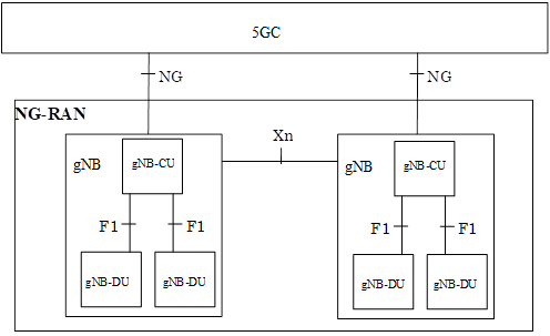
Figure 12: NG-RAN overall architecture
The EE KPI is limited to the gNB level (the 5G “BTS”), even if a gNB can be further divided into two physical entities: a gNB-CU (Centralized Unit) and gNB-DUs (Distributed Units) – which in turn might control more than one cell. This granularity (gNB level) is justified by an alignment with how EE KPI is defined for GERAN, UTRAN and E-UTRAN, and because the architecture depicted above is a logical architecture which may lead to various physical deployment architectures. The EE KPI definition for gNB should be independent from gNB physical architectures.
Consequently, both Data Volumes and Energy Consumption are calculated at gNB level.
For Energy Consumption, a key parameter is whether Virtualized Network Functions (VNFs) is used or not. For the non-VNF parts of base stations: regardless of whether these base stations are equipped with built-in or external sensors, their energy consumption is collected via XCU/DGU and/or VS-RMS and/or their EM/DM, as specified in TS 28.304 [42], TS 28.305 [43] and TS 28.306 [44]. This potentially applies to non-VNF core network elements as well. For VNF parts of base stations, the energy consumption of the VNF Functions is the energy consumption of the server(s) on which the VNF(s) run, minus the energy consumption of the servers when they are in idle mode, shown as Pidle on the next figure:
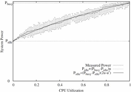
Figure 13: Power consumption of a server
This preliminary work has led to the corresponding normative work described below.
Energy Efficiency in 5G networks (EE_5G)
The overall framework on Energy Efficiency and Energy Saving in SA5 is provided in TS 28.310, an ‘Umbrella TS’ that covers different Energy Saving scenarios, including in the 5GC. The studies on Energy Efficiency in SA5 (in TR 32.856 [38] for Rel-15 and TR 32.972 [39] for Rel-16) have impacted the set of main SA5 normative documents, which are:
TS 28.540 [45] on “Management and orchestration; 5G Network Resource Model (NRM); Stage 1” and TS 28.541 [46] on “NRM Stage 2 and stage 3”
These NRM documents are not specific to energy saving. They describe the 5G network from a network management perspective: all entities of NR, NG-RAN, 5G Core Network (5GC) and network slice are described, including the variety of 5G RAN functions and features, covering management for NR connectivity options defined in TS 37.340 [47] and NG-RAN architectural options defined in TS 38.401 [48]; the variety of 5GC network functions and features defined in TS 23.501 [49]; and the network slice and network slice subnet.
TS 28.552 [50] on “Management and orchestration; 5G performance measurements”. This TS specifies the performance measurements for 5G networks including network slicing. Performance measurements for NG-RAN are defined in this document (clause 5.1), and some L2 measurement definitions are inherited from TS 38.314 [51]. The performance measurements for 5GC are all defined in this document (clause 5.2 to 5.6). Related KPIs are defined to those measurements are defined in TS 28.554 [52]. The performance measurements for NG-RAN applies also to NR option 3 in many cases, but not to the RRC connection related measurements which are handled by E-UTRAN for NR option 3 (those are measured according to TS 32.425 [53] and related KPIs in TS 32.451 [54]). A section is dedicated to Power, Energy and Environmental (PEE) measurements.
TS 28.554 [52] on “Management and orchestration; 5G end to end Key Performance Indicators (KPI)” is another key SA5 document, not specific to Energy Efficiency. It specifies the end-to-end Key Performance Indicators (KPIs) for the 5G network and network slicing. A significant section is dedicated to Energy Efficiency (EE) KPIs, as presented above, e.g. one KPI shows mobile network data energy efficiency in operational NG-RAN. It is the Data Volume (DV) divided by Energy Consumption (EC) of the considered network elements. The unit of this KPI is bit/J.
Release 17
In Release 17, no specific work on defining new functionalities for Energy Efficiency/saving was conduced.
Even the so-called “REFEC” feature (standing for: Enhanced Relays for Energy eFficiency and Extensive Coverage), despite its name, has very little to do with energy efficiency. It actually introduces a number of requirements on 5G ProSe relaying to TS 22.261 [55].
In SA5, TR 28.813 was further progressed, as well as new definitions of EE KPI in TS 28.554. TS 28.310 was aslo slightly updated.
Release 18 and Release 19
Release 18 and 19 are still ongoing at the time this document is written. As such, no stable summary can be provided.
All items being progressed are covered in the Work Plan, as presented in the References below.
References
3GPP Work Plan
See a listing of all work & study items here: https://www.3gpp.org/ftp/Information/WORK_PLAN/ .
References for Energy Efficiency and Energy Saving: Filter on Acronym with string "Energ"
Other References
[0] https://climate.ec.europa.eu/eu-action/climate-strategies-targets/2030-climate-targets_en#
[0a] https://www.itu.int/themes/climate/docs/report/02_ICTandClimateChange.html
[0b] https://www.statista.com/statistics/276629/global-co2-emissions/
[0c] https://ecotree.green/en/how-much-co2-does-a-tree-absorb
[2] https://www.linkedin.com/pulse/status-global-carbon-emissions-telecommunication-industry-woori-cho/
[3] https://www.orange-business.com/en/blogs/greening-telecoms-network#:~:text=The%20telecoms%20industry%20is%20responsible,like%20Southeast%20Asia%20and%20Africa.
[4] https://www.gsma.com/futurenetworks/wiki/energy-efficiency-2/
[5] TR 25.927: Study on Solutions for Energy Saving within UTRA Node B (Rel-10)
[6] TR 36.927: Study on Potential solutions for energy saving for E-UTRAN) Potential solutions for energy saving for E-UTRAN (Rel-10)
[7] TS 36.300 (RAN2): Evolved Universal Terrestrial Radio Access (E-UTRA) and Evolved Universal Terrestrial Radio Access Network (E-UTRAN); Overall description; Stage 2
[8] TR 32.826: Telecommunication management; Study on Energy Savings Management (ESM) (Rel-10)
[9] TR 32.834: Study on Operations, Administration and Maintenance (OAM) aspects of inter-Radio-Access-Technology (RAT) energy saving (Rel-11)
[10] TS 32.551: Energy Saving Management (ESM); Concepts and requirements
[11] TS 32.522: Self-Organizing Networks (SON) Policy Network Resource Model (NRM) Integration Reference Point (IRP): Information Service (IS)
[12] TS 32.762: Evolved Universal Terrestrial Radio Access Network (E-UTRAN) Network Resource Model (NRM) Integration Reference Point (IRP): Information Service (IS)
[13] TS 32.642: Configuration Management(CM); UTRAN network resources Integration Reference Point (IRP): Network Resource Model (NRM)
[14] TS 32.652 (SA5): Configuration Management(CM); GERAN network resources Integration Reference Point (IRP): Network Resource Model (NRM)
[15] TS 32.102 (SA5): Telecommunication management; Architecture
[16] TR 24.826 (CT1): Study on impacts on signalling between User Equipment (UE) and core network from energy saving
[17] TS 24.167 (CT1): 3GPP IMS Management Object (MO); Stage 3
[18] TS 24.216 (CT1): Communication Continuity Management Object (MO)
[19] TS 24.301 (CT1): Non-Access-Stratum (NAS) protocol for Evolved Packet System (EPS); Stage 3
[20] TS 24.237 (CT1): IP Multimedia (IM) Core Network (CN) subsystem IP Multimedia Subsystem (IMS) service continuity; Stage 3
[21] TS 23.251 (SA2): Network sharing; Architecture and functional description
[22] TS 24.303 (CT1): Mobility management based on Dual-Stack Mobile IPv6; Stage 3
[23] TS 24.302 (CT1): Access to the 3GPP Evolved Packet Core (EPC) via non-3GPP access networks; Stage 3
[24] TS 23.261 (SA2): IP flow mobility and seamless Wireless Local Area Network (WLAN) offload; Stage 2
[25] TS 23.682 (SA2): Architecture enhancements to facilitate communications with packet data networks and applications
[26] TS 25.413 (RAN3): UTRAN Iu interface Radio Access Network Application Part (RANAP) signalling
[27] TS 36.300: Evolved Universal Terrestrial Radio Access (E-UTRA) and Evolved Universal Terrestrial Radio Access Network (E-UTRAN); Overall description; Stage 2
[28] TS 25.413 (RAN3): UTRAN Iu interface; Radio Access Network Application Part (RANAP) signalling
[29] TS 36.413 (RAN3): Evolved Universal Terrestrial Radio Access Network (E-UTRAN); S1 Application Protocol (S1AP)
[30] TS 36.423: Evolved Universal Terrestrial Radio Access Network (E-UTRAN); X2 Application Protocol (X2AP)
[31] TS 48.018 (GERAN): Serving GPRS Support Node (SGSN); BSS GPRS protocol (BSSGP)
[32] TR 23.866 (SA2): Study on system improvements for energy efficiency
[33] TR 36.887 (RAN3): Evolved Universal Terrestrial Radio Access Network (E-UTRAN); Study on energy saving enhancement for E-UTRAN
[34] TR 45.926 (GERAN): Solutions for GSM/EDGE Base Transceiver Station (BTS) energy saving
[35] TS 32.425 (SA5): E-UTRAN Performance Management (PM); Performance measurements
[36] ETSI ES 203 228 (ETSI TC EE): Environmental Engineering (EE); Assessment of mobile network energy efficiency
[37] ETSI ES 202 336-12 (ETSI TC EE): ICT equipment power, energy and environmental parameters monitoring information model
[38] TR 32.856 (SA5): Study on Operations, Administration and Maintenance (OAM) support for assessment of energy efficiency in mobile access networks
[39] TR 32.972 (SA5): Telecommunication management; Study on system and functional aspects of energy efficiency in 5G networks
[40] TS 28.550 (SA5): Management and orchestration; Performance assurance
[41] TS 28.552 (SA5): Management and orchestration; 5G performance measurements
[42] TS 28.304 (SA5): Control and monitoring of Power, Energy and Environmental (PEE) parameters Integration Reference Point (IRP); Requirements
[43] TS 28.305 (SA5): Control and monitoring of Power, Energy and Environmental (PEE) parameters Integration Reference Point (IRP); Information Service (IS)
[44] TS 28.306 (SA5): Control and monitoring of Power, Energy and Environmental (PEE) parameters Integration Reference Point (IRP); Solution Set (SS) definitions
[45] TS 28.540 (SA5): Management and orchestration; 5G Network Resource Model (NRM); Stage 1
[46] TS 28.541 (SA5): Management and orchestration; 5G Network Resource Model (NRM); Stage 2 and Stage 3
[47] TS 37.340 (RAN2): NR; Multi-connectivity; Overall description; Stage-2
[48] TS 38.401 (RAN3): NG-RAN; Architecture description
[49] TS 23.501 (SA2): System architecture for the 5G System (5GS)
[50] TS 28.552 (SA5): Management and orchestration; 5G performance measurements
[51] TS 38.314 (RAN2): NR; Layer 2 measurements
[52] TS 28.554 (SA5): Management and orchestration; 5G end to end Key Performance Indicators (KPI)
[53] TS 32.425 (SA5): Telecommunication management; Performance Management (PM); Performance measurements Evolved Universal Terrestrial Radio Access Network (E-UTRAN)
[54] TS 32.451 (SA5): Telecommunication management; Key Performance Indicators (KPI) for Evolved Universal Terrestrial Radio Access Network (E-UTRAN); Requirements
[55] TS 22.261 (SA1): Service requirements for the 5G system